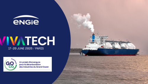
Viva Technology | 10/06/2026
In the face of the climate emergency, certain industrial sectors are confronted with so-called “hard-to-abate”...
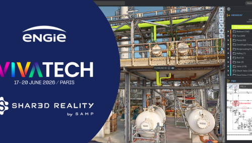
Viva Technology | 08/06/2026
At Viva Technology, ENGIE is showcasing on its stand a range of innovative partners that are reinventing industry and...
Podcasts | 04/06/2026
Learn more about electrification, sustainable carbon solutions, and cutting-edge technologies related to the EU-funded...